[SOBAC Home Page] [Bob Jonkman's Home Page] [Site Map]
Related pages: [Token Ring specifications] [NET.CFG] [IBM] [IBM Networking | Token-Ring Adapters] [Novell]
In this page: [Optimal Settings] [Switch Position] [Adapter ROM Address] [Interrupt] [I/O Port] [Shared RAM Size] [Data Rate] [Unit prefixes]
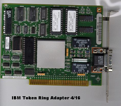
IBM Token Ring Adapter 4/16
Switch Settings

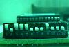 The standard ISA IBM Token Ring Adapter has a switch bank of 12 switches. On an IBM computer running a DOS or Windows 3.1 environment where the address range from E000-EFFF is used by the BASIC ROM and the address range F000-FFFF is used by the system BIOS ROM, the optimal settings for the Token Ring Adapter RAM is at DC00-DFFF and ROM is at DA00-DBFF. For clone PCs that have no BASIC ROM it would be better to place the adapter RAM and ROM as low as possible. The exact location depends on whether there is Video ROM present. It is even possible to tuck the adapter RAM and ROM in an unused video text area. Since most computers have a colour monitor, this is most likely the monochrome text area at B000-B7FF. The same settings can be used for the Microchannel IBM Token Ring Adapter 4/16 A, but the settings are configured with the reference utility, not switches on the adapter.
These ROM locations are not documented in the manual packed with the IBM Token Ring card. In fact, the function of the switches to set memory locations aren't documented there. I have determined the switch functions by comparing the bit patterns of the two high-order bytes with the documented ROM locations, and extrapolated the function of the remaining settings from there. The behaviour of the card is consistent with these values, but neither I (Bob Jonkman) nor SOBAC Microcomputer Services will be responsible for any failures incurred through the use of the switch settings documented here.
Only the Adapter ROM address can be set with switches on the Token Ring Adapter. The Shared RAM location is specified by a parameter on the command line of the token ring driver, or a configuration file. Some drivers (like TOKEN.LAN for a Netware server) will not allow alternate configurations, and expects the Shared RAM to be at the default D800-DBFF. In this case you should also configure the Adapter ROM to be at the default DC00-DDFF.
Note that the Adapter ROM Address table is not exhaustive, but only lists the most common settings. All addresses in this document refer to segment addresses in upper memory (above 640 KibiBytes, below 1 Mebibyte).
The following switch settings have been designed to optimize upper memory where E000-FFFF is unavailable. A NET.CFG file for these settings is available for workstations on a Novell Netware network. The memory addresses in NET.CFG refer to absolute addresses, not segment addresses, hence the extra zeroes.
^ Optimal Switch Settings
|
ROM Address
|
Interrupt
|
I/O Port
|
Shared RAM
|
Data Rate
|
|
Switch number
|
1
|
2
|
3
|
4
|
5
|
6
|
7
|
8
|
9
|
10
|
11
|
12
|
|
Optimal
|
OFF
|
ON
|
OFF
|
OFF
|
ON
|
OFF
|
ON
|
ON
|
OFF
|
OFF
|
ON
|
OFF
|
|
AROM=DA00-DBFF
|
IRQ=2
|
I/O=A20 (PRI)
|
ARAM=16 KibiBytes
|
16 Mib/s
|
|
IBM Default
|
OFF
|
ON
|
OFF
|
OFF
|
OFF
|
ON
|
ON
|
ON
|
OFF
|
ON
|
ON
|
ON
|
|
AROM=DC00-DDFF
|
IRQ=2
|
I/O=A20 (PRI)
|
ARAM=8 KibiBytes
|
Mib/s
|
The following tables list the functions and common settings for each set of switches.
^ Switch Position
|
OFF
|
ON
|
|
UP
|
DOWN
|
^ Adapter ROM address
|
1
|
x
|
x
|
x
|
x
|
x
|
x
|
0
|
Bit Pattern of First Two Digits of Upper Memory Segment
OFF=1, ON=0
|
|
1
|
2
|
3
|
4
|
5
|
6
|
|
Switch Position
|
|
ON
|
OFF
|
OFF
|
OFF
|
OFF
|
ON
|
|
B400-B6FF "Mono Text"
(16K Shared RAM should be set to B000-B3FF)
Used when the Monochrome Text area is available,
no monochrome monitor will be attached to the system
|
|
OFF
|
ON
|
ON
|
ON
|
OFF
|
ON
|
|
C400-C5FF "Low Cxxx"
(16K Shared RAM should be set to C000-C3FF)
Used when no Video ROM is present
|
|
OFF
|
ON
|
ON
|
OFF
|
OFF
|
ON
|
|
CC00-CDFF "Video Cxxx"
(16K Shared RAM should be set to C800-CBFF)
Used when Video ROM=C000-C7FF
|
|
OFF
|
ON
|
OFF
|
OFF
|
ON
|
OFF
|
|
DA00-DBFF "High Dxxx"
(16K Shared RAM should be set to DC00-DFFF)
|
|
OFF
|
ON
|
OFF
|
OFF
|
OFF
|
ON
|
|
DC00-DDFF "IBM Default"
(16K Shared RAM default is D800-DBFF
|
^ Interrupt
|
7
|
8
|
Switch Position
|
|
ON
|
ON
|
IRQ=2
|
|
ON
|
OFF
|
IRQ=3
(usually COM4)
|
|
OFF
|
ON
|
IRQ=6
(usually Floppy Drive)
|
|
OFF
|
OFF
|
IRQ=7
(usually LPT1)
|
^ I/O Port
|
9
|
Switch Postion
|
|
OFF
|
A20 (Primary)
(this setting conflicts with the standard audio card I/O port of 220
set your audio card to an alternate I/O port)
|
|
ON
|
A40 (Secondary)
|
^ Shared RAM size
|
10
|
11
|
Switch Position
|
|
ON
|
ON
|
8 KibiBytes
|
|
OFF
|
ON
|
16 KibiBytes
|
|
ON
|
OFF
|
32 KibiBytes
|
|
OFF
|
OFF
|
64 KibiBytes
|
^ Data Rate
|
12
|
Switch Position
|
|
ON
|
4 Mib/s
|
|
OFF
|
16 Mib/s
|
^ What are these units?
This article now uses the terms "Kibibyte" and "Mebibyte". These units use the prefixes "Ki" (or "Kibi", short for "kilo-binary") to represent 210 (or 1024) and "Mi" (or "Mebi", short for "Mega-binary") to represent 220 (or 1,048,576). This reduces the ambiguity for computer-related terms, since the SI prefix "k" or "kilo" actually means 103 (or 1000) and "M" or "Mega" actually means 106 (or 1,000,000).
See the Wikipedia entry for Byte/Prefixes for a list of all the binary prefixes.
In this page: [Top of Page] [Optimal Settings] [Switch Position] [Adapter ROM Address] [Interrupt] [I/O Port] [Shared RAM Size] [Data Rate] [Unit prefixes]
Related pages: [Token Ring specifications] [NET.CFG] [IBM] [IBM Networking | Token-Ring Adapters] [Novell]
[SOBAC Home Page] [Bob Jonkman's Home Page] [Site Map]
All text and pictures Copyright © 1998-2002 SOBAC Microcomputer Services unless otherwise attributed
This page was last updated on Sunday, 13 October 2002 by Bob Jonkman
 The standard ISA IBM Token Ring Adapter has a switch bank of 12 switches. On an IBM computer running a DOS or Windows 3.1 environment where the address range from E000-EFFF is used by the BASIC ROM and the address range F000-FFFF is used by the system BIOS ROM, the optimal settings for the Token Ring Adapter RAM is at DC00-DFFF and ROM is at DA00-DBFF. For clone PCs that have no BASIC ROM it would be better to place the adapter RAM and ROM as low as possible. The exact location depends on whether there is Video ROM present. It is even possible to tuck the adapter RAM and ROM in an unused video text area. Since most computers have a colour monitor, this is most likely the monochrome text area at B000-B7FF. The same settings can be used for the Microchannel IBM Token Ring Adapter 4/16 A, but the settings are configured with the reference utility, not switches on the adapter.
